 |
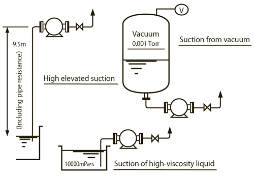
| 1. Suction Capacity (Max. -9.5 m) |
With its high self-priming capability,
this unit is ideal for suction of fluid from an underground tank,
suction from a vacuum tank, etc.
 |
| 2. |
Suction Pressure (Max. 5.0 MPa) |
| Even if there is back pressure on the suction side, a seal-less gear pump or a double shaft seal pump will be able to handle it. |
| 3. |
Discharge Pressure (Max. 10.0 MPa) |
Pumps that can withstand high pressure can be manufactured.
These feature little change of capacity for changes of discharge pressure.
Products approved for high-pressure gas can also be manufactured. Contact us for details. |
| 4. |
Sending liquid viscosity (0.3 mPa・s to 1 million mPa・s) |
Any liquid can be pumped, from low viscosity to very high viscosity.
Liquid can be pumped if the relationship between the rotation speed of the pump and the piping for viscosity is appropriate.
For viscosity exceeding the above values, please consult us. |
| 5. |
Capacity (Minute amount of 20 cc/min to large-capacity 5000 L/min) |
A wide variety of gear pumps from small to large can be manufactured.
The capacity of a gear pump fluctuates in proportion to the rotation speed.
By leveraging the quantitative capability, it can be used as a quantitative pump.
Also, the capacity can be made variable with a speed variator, inverter drive, etc. |
| 6. |
Low to high temperatures can be handled (-50 °C to +350 °C) |
Thermal oil, polymer, pitch, etc. Maximum temperature: 350 °C
Brine, ammonia, engine oil, Automatic Transmission Fluid (ATF), etc. Minimum temperature: -50 °C
Various temperature situations can be handled. |
| 7. |
Wide range of materials can be combined
Pump materials (FC, FCD, SC, SUS, ALBC, hastelloy, etc.)
(Acid, alkali, solvent, etc. can be handled) |
| For the case, cover, gear, shaft, side plate, metal, or shaft seal, various materials can be combined. |
| 8. Structure that can be freely combined |
(1) Shaft seal
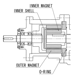
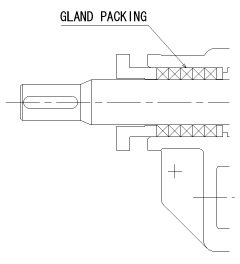
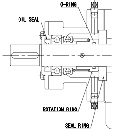
We design and manufacture various kinds of shaft seals in-house.
The most appropriate shaft seal can be selected for the pumped liquid, or specification and structure of the pump. |
 |
 |
| Seal-less |
Gland packing |
No leakage.
For petrochemicals, chemical liquids,
waste liquids, hazardous substances, etc. |
Can be used for any liquid from low to high viscosity. |
 |
 |
Single mechanically sealed
Outside-type KM type |
Single mechanically sealed
Inside-type M type/EM type |
| Used for SUS pump for chemical liquids, chemicals, liquid foods, etc. |
Standard type for oil in general,
low viscosity oil and liquids. |
 |
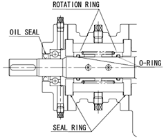 |
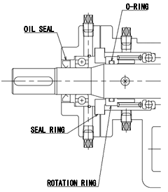
Double bellows mechanically sealed
Tv2 type |
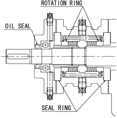
Double mechanically sealed
M2 type |
Vacuum-resistant suction liquid,
air hardening solution, warm liquid,
solvent, resin, varnish polymer, etc. |
Vacuum-resistant suction liquid,
air hardening solution, resin, varnish polymer, etc. |
 |
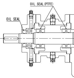 |
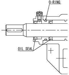
Oil sealed
S type (NBR, FKM) |
Teflon oil sealed
S2 type (PTFE) |
| Used when leakage prevention of low viscosity, oil, or liquid is necessary.
|
Can be used if there are problems with traditional seals when used with solvent, thermal hardening varnish, resin, etc. |
 |
|
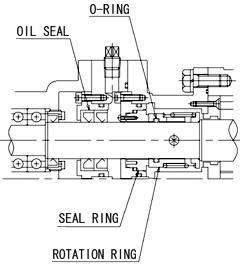
Single mechanically sealed
Inside type/oil seal MS type |
|
For non-wetted outer shaft bearing
OH type oil in general - Chemical liquids,
low viscosity liquid, waste liquid, etc. |
|
(2) Safety valve
A built-in safety valve that is built inside the pump, or an independent safety valve installed on the piping can be selected. |
(3) Pump jacket
A jacket for heating/cooling can be fitted on the case, shaft seal, or whole pump. |
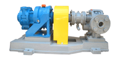
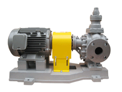
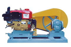
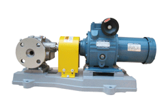
| 9. Driving method of pump |
| We will meet your request. |
 |
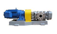 |
| Air motor direct drive |
Geared motor direct drive |
| |
Up to 1 million mPa・s |
 |
 |
| Motor direct drive |
Engine-drive |
4P motor, up to approx. 250 mPa・s
6P motor, up to approx. 1000 mPa・s |
|
 |
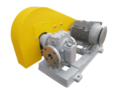 |
| Speed variator direct drive |
V belt drive |
| The rotation speed can be made variable depending on the capacity.
|
4P motor, up to approx. 5000 mPa・s
6P motor, up to approx. 10000 mPa・s |
| * |
Consult us for specifications other than those mentioned above. |
| * |
The range of each specification may change depending on conditions. Contact us for details. |
|


